4 Transistor Photo Detector Circuit Using An Lm339 : Lm339, lm239, lm2901, lm2901v, ncv2901, mc3302.
4 Transistor Photo Detector Circuit Using An Lm339 : Lm339, lm239, lm2901, lm2901v, ncv2901, mc3302.. The lm311 voltage comparator can be used for these applications as well and also has a number of unique features. A missing pulse detector circuit (watchdog timer) is often used to determine if a system is properly operating. First let us consider the internal connection of four comparators in the device as shown below. This circuit is really built for demonstration purposes, just so to show you how to connect an lm339 and how it works. Short circuits from outputs to vcc can cause excessive heating and.
Lm339 (quad differential comparator) consist of four independent voltage comparators. First comparator ic1a is used for detecting the peak of the input signal. The battery discharges are simulated with a potentiometer 5k. Best water tank level indicator, circuit use 2003 ic very easy 7 led. We set the trigger level.
Audio level indicator using LM339 | Circuit diagram, Audio ... from i.pinimg.com Lm339 is a dual comparator. Available at no cost, pspice for. The battery discharges are simulated with a potentiometer 5k. Ti's lm339 is a quad differential comparator. Operates from 5v dc single supply. Using lm339 can easily form various voltage comparator circuits and oscillator circuits. The lm311 voltage comparator can be used for these applications as well and also has a number of unique features. Now let us take a single comparator from the four and construct a simple application circuit as show below.
All of the circuits on the pcb are configured so with the intention of as the photosensors are dark, the output of the 556 timers want stay peak.
The post discuses 4 simple motion detector circuits using op amp and transistor. This is a battery monitor circuit with zener diodes & quad differential comparator lm 339. First let us consider the internal connection of four comparators in the device as shown below. Lm239/lm339, e/lm2901, e, v mc3302. The lm339 input detection voltage levels for the circuit as shown is set at 1/2 of the supply voltage. The lm311 voltage comparator can be used for these applications as well and also has a number of unique features. It's operation is similar to the lm339/393 circuit. Lm339 based peak detector circuit.simple and easy to construct. Now let us take a single comparator from the four and construct a simple application circuit as show below. Short circuits from outputs to vcc can cause excessive heating and. Available at no cost, pspice for. This is a battery monitor circuit. Dual comparator ic lm393 is the heart of this circuit.
First let us consider the internal connection of four comparators in the device as shown below. A missing pulse detector circuit (watchdog timer) is often used to determine if a system is properly operating. U1 charges c1 through d1 at the falling edge of each clock pulse, keeping its voltage above the logic threshold of u4 and thus the out voltage. This circuit is really built for demonstration purposes, just so to show you how to connect an lm339 and how it works. The battery discharges are simulated with a potentiometer 5k.
Darkness detector circuit with audio output using 555 ... from electronicsarea.com Dual comparator ic lm393 is the heart of this circuit. The circuit schematic for the lm339 quad voltage comparator circuit that we are going to build is shown below. It's operation is similar to the lm339/393 circuit. The issue delay period of each one 556 timer can be tainted by selecting as it should be combination ideals representing the r7/c2, r8/c3. The suitability of its products for any particular purpose, nor does on semiconductor assume any liability arising out of the application or use of any product or circuit, and specifically. We use a lm339 quad comparator ic. First let us consider the internal connection of four comparators in the device as shown below. Now let us take a single comparator from the four and construct a simple application circuit as show below.
The issue delay period of each one 556 timer can be tainted by selecting as it should be combination ideals representing the r7/c2, r8/c3.
We use a lm339 quad comparator ic. In this circuit, there are 4 different color. The post discuses 4 simple motion detector circuits using op amp and transistor. Dual comparator ic lm393 is the heart of this circuit. It's operation is similar to the lm339/393 circuit. Using lm339 can easily form various voltage comparator circuits and oscillator circuits. The circuits shown are based on the lm339 quad voltage comparator or the lm393 dual voltage comparator. Lm339 based peak detector circuit.simple and easy to construct. This circuit is really built for demonstration purposes, just so to show you how to connect an lm339 and how it works. The battery discharges are simulated with a potentiometer 5k. The issue delay period of each one 556 timer can be tainted by selecting as it should be combination ideals representing the r7/c2, r8/c3. Lm239/lm339, e/lm2901, e, v mc3302. This is a battery monitor circuit with zener diodes & quad differential comparator lm 339.
We use a lm339 quad comparator ic. First let us consider the internal connection of four comparators in the device as shown below. We set the trigger level. The circuits shown are based on the lm339 quad voltage comparator or the lm393 dual voltage comparator. The lm339 input detection voltage levels for the circuit as shown is set at 1/2 of the supply voltage.
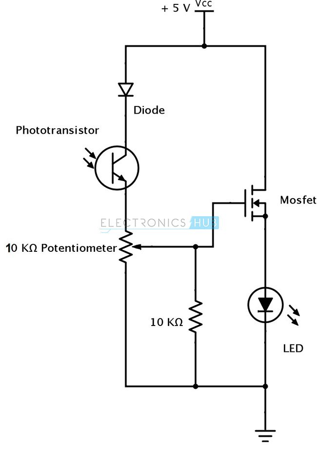
IR (Infrared) Obstacle Detection Sensor Circuit from www.electronicshub.org Dual comparator ic lm393 is the heart of this circuit. The lm339 input detection voltage levels for the circuit as shown is set at 1/2 of the supply voltage. Lm339 (quad differential comparator) consist of four independent voltage comparators. The circuit schematic for the lm339 quad voltage comparator circuit that we are going to build is shown below. For example starting with the diodes then resistors, ic's, transistors, capacitors and terminal blocks. Now let us take a single comparator from the four and construct a simple application circuit as show below. Lm339 is a dual comparator. This is a battery monitor circuit.
How to use lm339 voltage comparator.
It's operation is similar to the lm339/393 circuit. In this circuit, there are 4 different color. Dual comparator ic lm393 is the heart of this circuit. We also discuss the pinout details of the standard passive infrared the first circuit uses an op amp, while the second design works with a single transistor and relay for detecting the ir radiation from a moving human. The lm339 input detection voltage levels for the circuit as shown is set at 1/2 of the supply voltage. Lm339 is a dual comparator. The suitability of its products for any particular purpose, nor does on semiconductor assume any liability arising out of the application or use of any product or circuit, and specifically. A missing pulse detector circuit (watchdog timer) is often used to determine if a system is properly operating. How to use lm339 voltage comparator. For example starting with the diodes then resistors, ic's, transistors, capacitors and terminal blocks. Now let us take a single comparator from the four and construct a simple application circuit as show below. Lm339 (quad differential comparator) consist of four independent voltage comparators. Short circuits from outputs to vcc can cause excessive heating and.
Related : 4 Transistor Photo Detector Circuit Using An Lm339 : Lm339, lm239, lm2901, lm2901v, ncv2901, mc3302..